Model Particle Accelerator
July 21st, 2023 / 15min read
Last updated December 24, 2023
July 21st, 2023 / 15min read
Last updated December 24, 2023
This project was originally a final project submission for the Computational Physics class I took during my undergrad sophomore year at Tufts. The aim of this project was to construct an oscillator, a physical system that displays periodic motion around an equilibrium point and possesses a restoring force that brings it back to its equilibrium position after displacement.
To meet this objective, I built a model particle accelerator. Although creating an oscillator was the main focus of the project, I personally wanted to dabble in experimental physics and incorporate that interest in my project. Furthermore, the selection of a model particle accelerator was motivated by my desire to integrate embedded/lower level programming with physics, thus bridging the gap between hardware and software engineering.
The culmination of my efforts resulted in a device that emulates a crucial instrument in high-energy particle physics research. Additionally, this project focuses on studying energy transfer from the accelerator to the particle of interest and optimizing the overall efficiency of this energy transfer. The construction of the model particle accelerator was achieved through the use of microcontrollers, sensors, common hardware items, and 3D printed objects.
The underlying mechanics of this model synchrotron are relatively straightforward: as the ball moves along a transparent tube, it encounters photogates. The photogates gauge the ball's instantaneous velocity using the distance between their sensors and their angular positioning. It must be noted that when an object moves in a circular path, its linear velocity at any point is tangential to the circle at that point. Angular velocity helps us establish a connection between the angular motion (rotation) and the linear motion (translation) of the object, thus allowing us to measure its instantaneous velocity at a specific point.
By leveraging our understanding of the solenoid's length and the distance between the photogate and the electromagnet, we can accurately ascertain the exact times \(t_3\) and \(t_4\) at which the ball reaches those locations, respectively. Armed with this information, we can then determine the optimal timing for applying an electric current to the electromagnets. This activation of the magnetic field, in turn, propels the particle forward.

In regards to the magnetic field of the solenoid, we can calculate the force of the magnetic field on the particle. To describe the interaction between charged particles and magnetic fields, we use the Lorentz Force Law. The Lorentz Force Law describes the force experienced by a charged particle moving in an electromagnetic field. It captures the combined effect of electric and magnetic forces acting on the charged particle.
\(\vec{F} = q\vec{E} + q\vec{v} \times \vec{B}\)
However, since there will be no electric force applied to the particle and assuming the metal ball has a neutral charge, this equation is reduced to
\(\vec{F} = \vec{v} \times \vec{B}\)
where \(\vec{F}\) is the force experienced by the charged particle, \(\vec{v}\) is the velocity of the particle, and \(\vec{B}\) is the strength of the magnetic field. The vector cross product \(\vec{v} \times \vec{B}\) indicates that the force is perpendicular to both \(\vec{v} \times \vec{B}\). Using Ampere's Law applied to a solenoid, the strength of the magnetic field can be described by
\(\vec{B} = \mu n I\)
where \(\mu\) is the relative permeability of the core (air), \(n\) is the turn density of the solenoid—the number of turns divided by the length of the solenoid or \(N/L\) (turns/m), and \(I\) (amperes) is the current in the solenoid.
It must be noted that although the steel ball will have a neutral charge entering the solenoid, the ball will be temporarily magnetized through electromagnetic induction. This occurs due to the alignment of tiny atomic magnetic domains within magnetic materials like iron or nickel. These domains, composed of atoms with aligned magnetic moments, usually have random orientations. This results in a weak overall magnetic effect.
When the solenoid's magnetic field influences the ball, its atomic domains align with the field's direction. Domains aligned with the field grow, while those opposing it diminish. This cumulative realignment creates a stronger magnetic field within the ball itself, thus temporarily magnetizing the ball. However, this effect fades once the ball leaves the magnetic field.
Hence, it's anticipated that the steel ball won't travel through the entire powered solenoid since it will swiftly be drawn to the center once it becomes fully magnetized. To solve this, the electromagnet will remain activated until the ball reaches the middle of the solenoid. Beyond that point, the ball will be propelled by its previous attraction to the solenoid’s magnetic field, free from its temporary magnetization in hopes of minimizing its negative impact on its acquired kinetic energy.
Hardware Breakdown
**NA implies the material was obtained for free from an unconventional source (university, workshop scraps, etc.)
Experimental Values
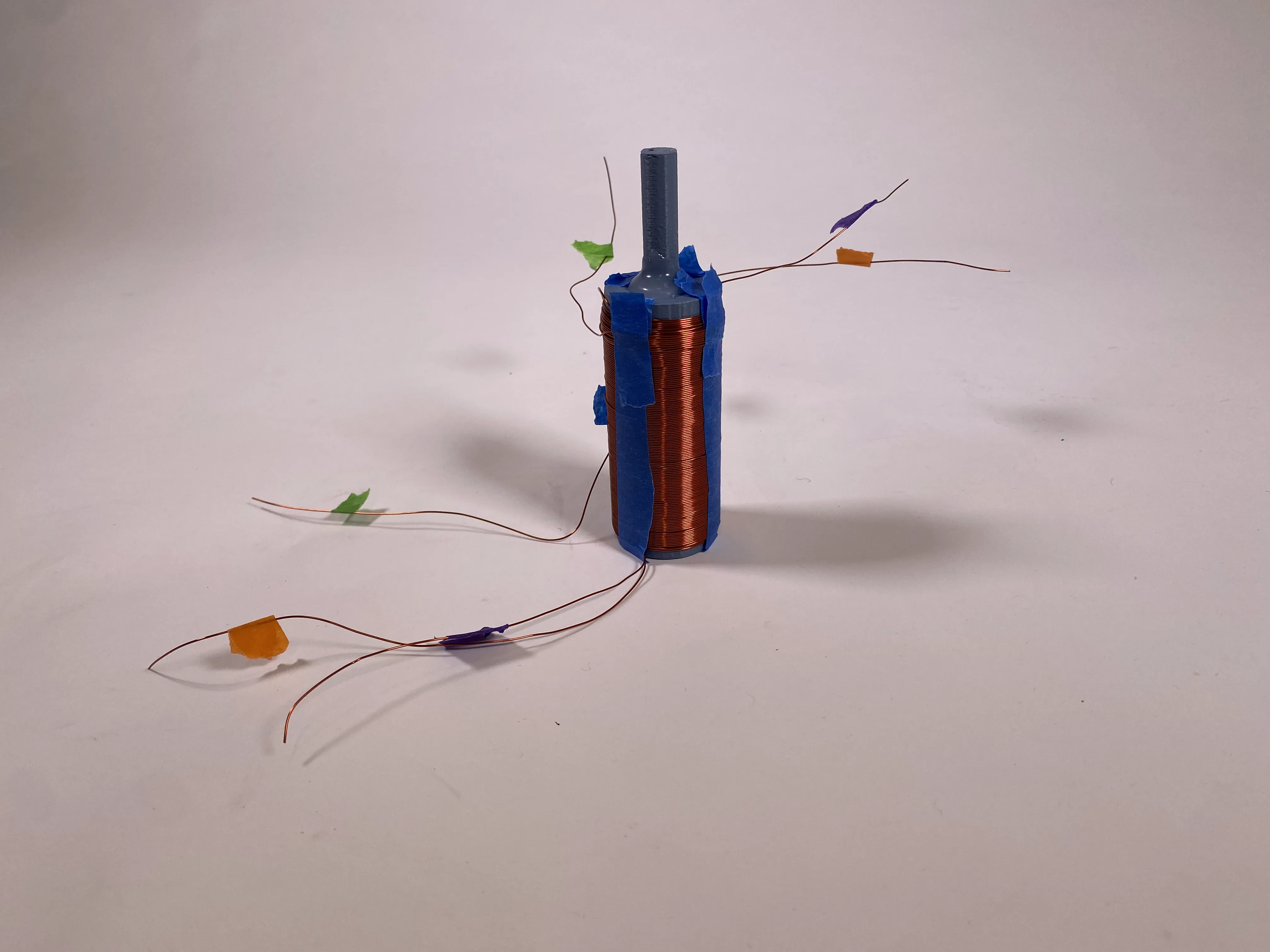
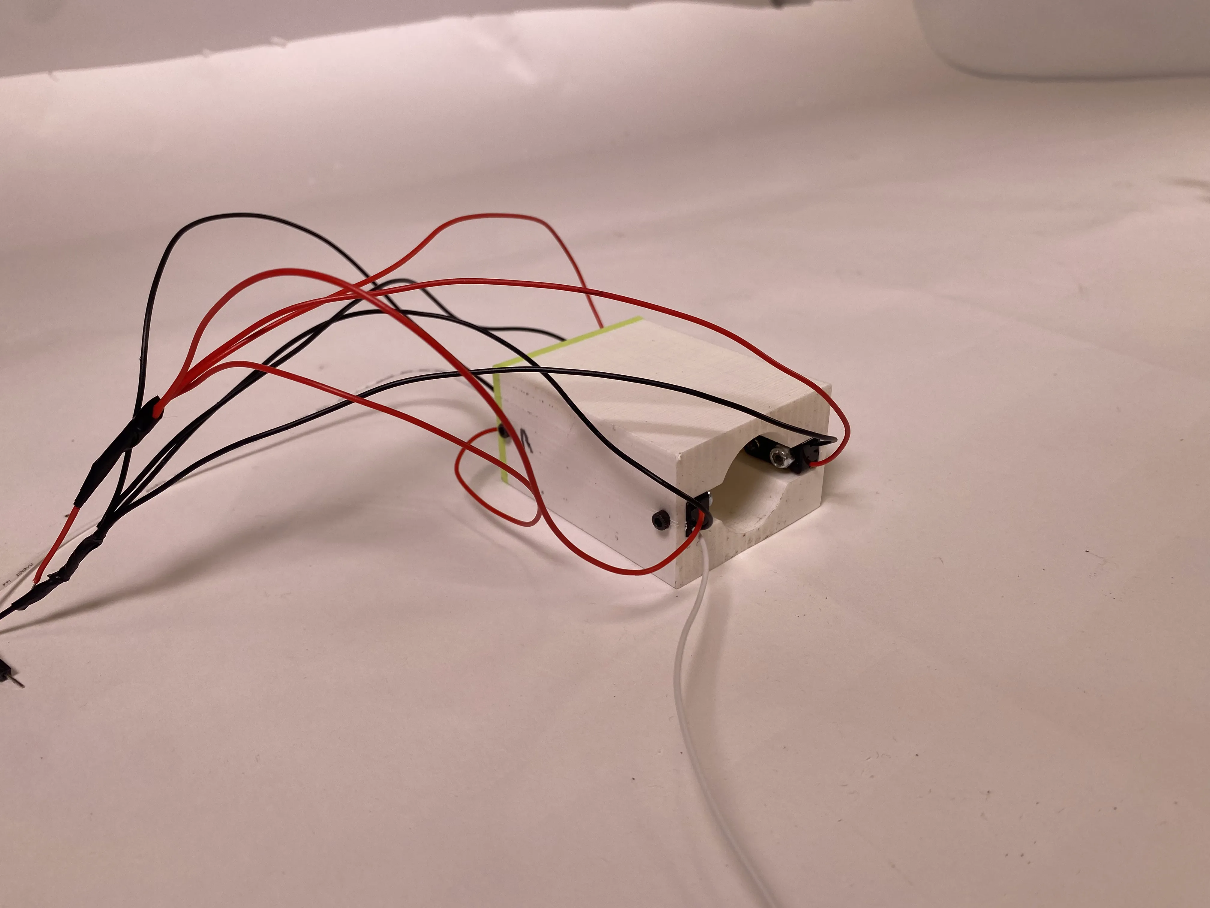
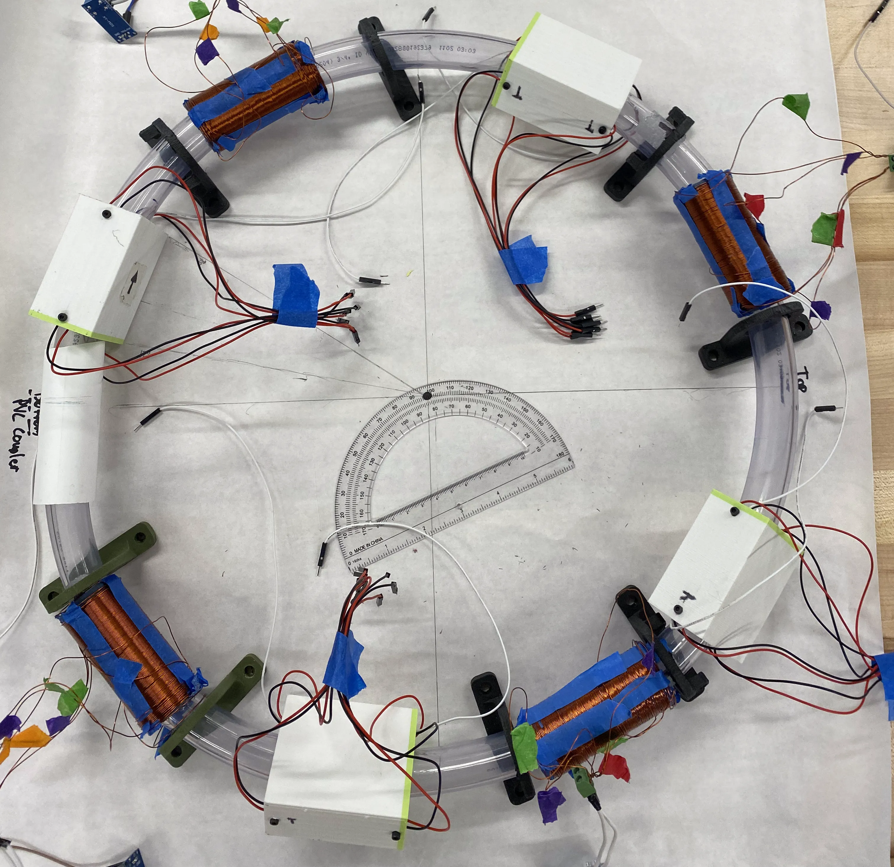
The particle accelerator's final design is depicted in the figure below. Angular spacing between components was employed to maintain a consistent distance between each item. In essence, it features a looped, transparent plastic tube adorned with four photogate-electromagnet pairs along its external surface. These pairs serve a dual purpose: they gauge the particle's speed and meticulously synchronize solenoid activation for precise acceleration. The photogates consist of two pairs of beambreak (IR) sensors fixed 33 millimeters away from each other inside a 3D printed compartment. This print was designed to fit the sensor’s exact width, height, and length. A screw was necessary to fix it in place. As for the electromagnet, a 3D printed hollow cylinder with an inner diameter slightly greater than ⅝ inches was used to coil the copper wire into a solenoid.

At the heart of this configuration are the photogates. Each photogate has its pair of sensors positioned a specific distance away from each other within the compartment. This calibrated distance holds the key to accurate velocity calculation, pivotal in deriving times \(t_3\) and \(t_4\). Every constituent of the particle accelerator occupies a predetermined position along the device's circular trajectory. This spatial arrangement ensures not only the computability of \(t_3\) and \(t_4\) but also allows for the temporal requirements essential for accurate computations as the particle's velocity escalates within the accelerator.
The software architecture was programmed to harmonize with the hardware's design. At its core, the program takes on the responsibility of managing active photogate-electromagnet pairs using a generic queue data structure. This orchestration ensures that the pair positioned at the forefront of the queue plays the "active" role, either steering particle acceleration or standing ready for its entry into the acceleration zone. Upon entry into the "active" zone, the particle's velocity is computed, validated through its traversal of the photogate. This event is triggered through a signal to the Arduino, facilitated by the modification of the state of each IR sensor. The state of a sensor shifts when an object crosses its beam.
A pivotal aspect here is the synchronization: the equality of states among both sensors within the photogate denotes the successful passage of the particle through the photogate. At this point, the Arduino takes the reins, initiating a countdown to \(t_3\) and \(t_4\). This countdown, in turn, triggers the precise activation and deactivation of a MOSFET module that connects an external power supply to its respective electromagnet. This module is used as a switch in this case; when the countdown timer is at time \(t_3\), the MOSFET allows current to flow from the external power supply to the electromagnet. Conversely, at time \(t_4\), the MOSFET cuts the electromagnet from the power supply. Upon the particle's exit from the "active" zone, the pair is popped off the queue, relinquishing its "active" status for the next pair in line.

In summation, the particle accelerator's physical design cohesively harmonizes with its software architecture. This synergy encapsulates a meticulous interplay between hardware and software, underscoring the precision requisite for efficiently propelling particles along the accelerator's circular course.
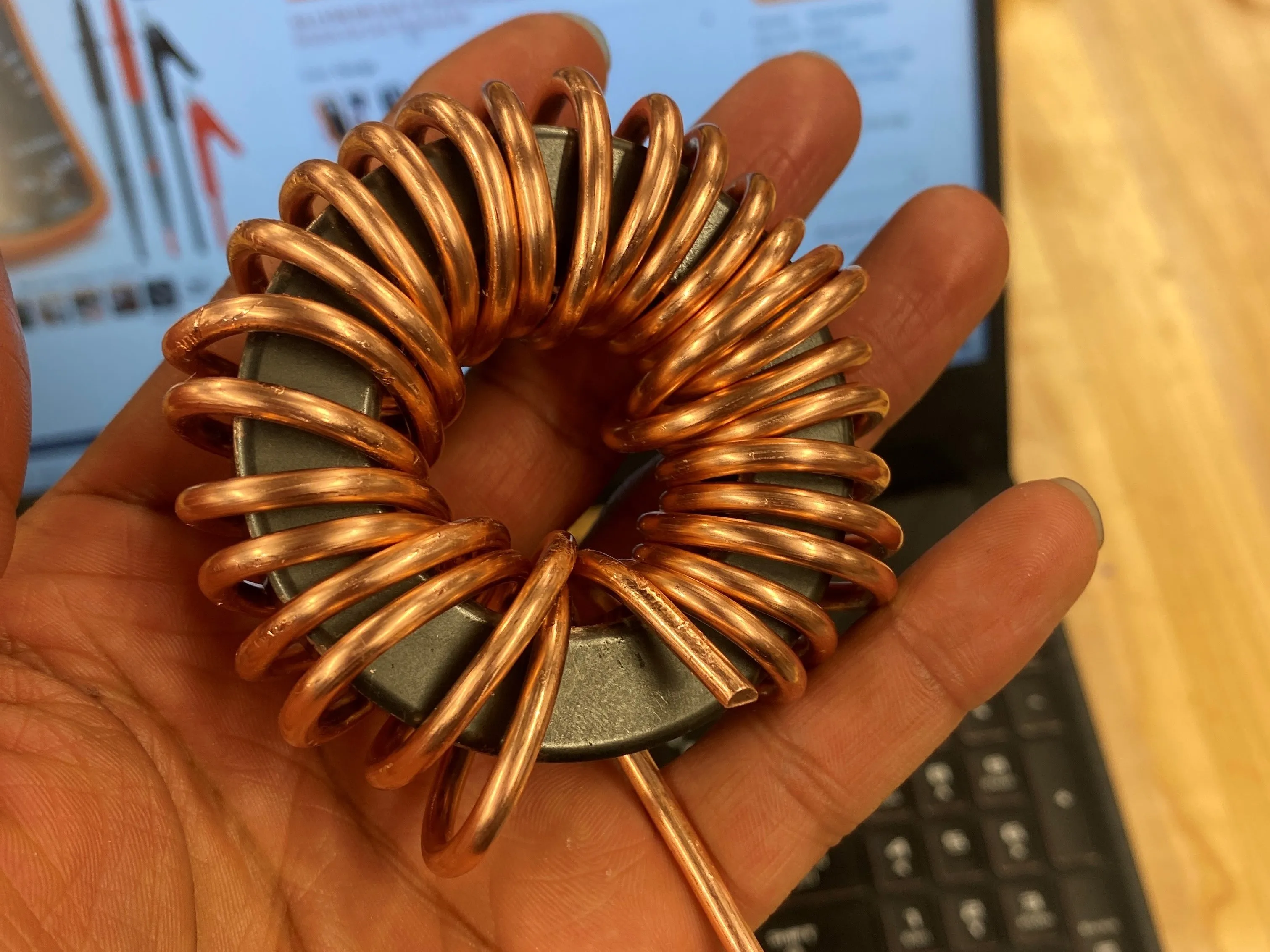
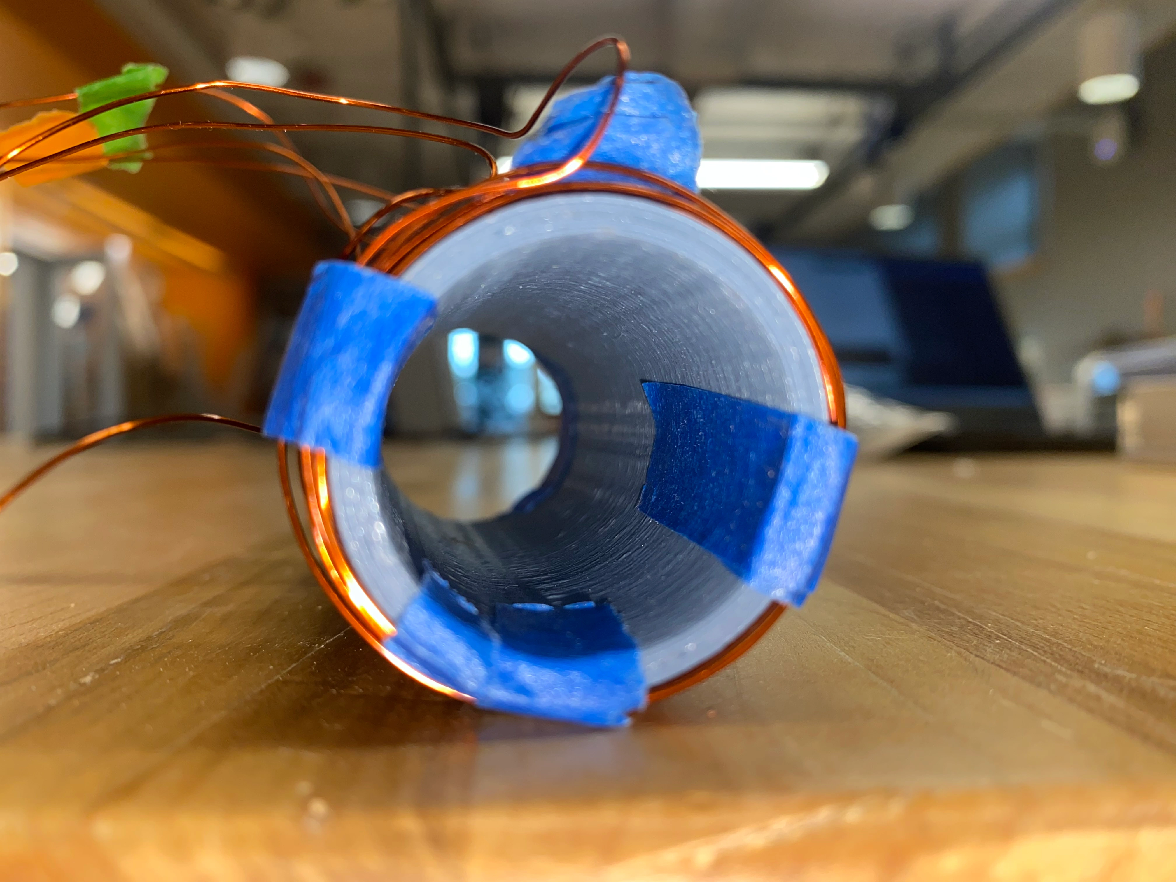
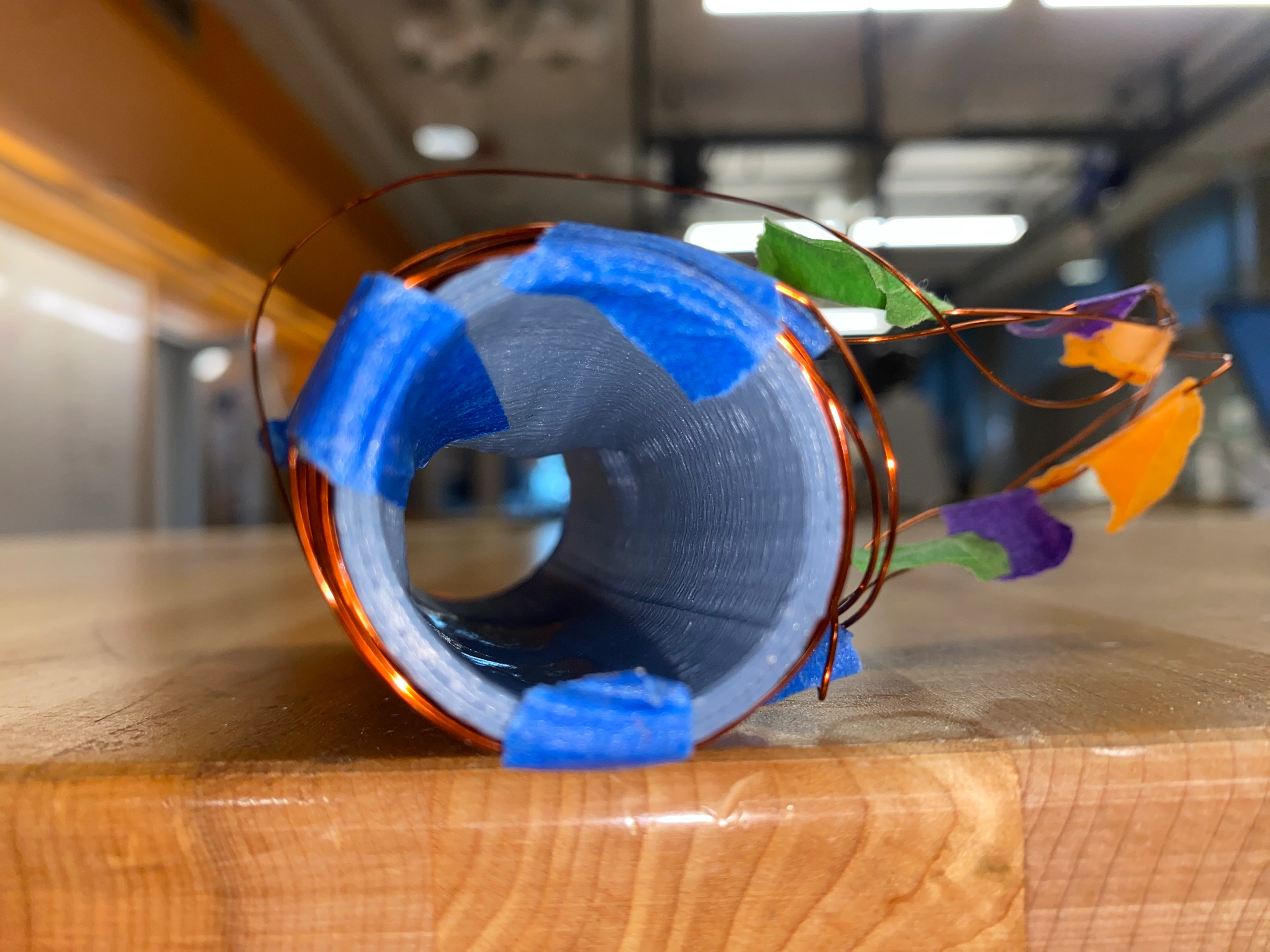
The model synchrotron was able to successfully accelerate the steel ball. However, operational time was limited to just a couple minutes before necessitating a shutdown due to overheating components. Among the solenoids, the cylinders encasing the magnet wire coils suffered distortion from the heat generated by the copper wires conducting current. This distortion rendered the solenoids unfit for reattachment to the particle accelerator, effectively designating this device as a single-use apparatus. Below are pictures of one of the lesser damaged solenoids.
Regardless, the successful construction of the model particle accelerator marks a significant achievement in my pursuit of understanding and simulating complex scientific phenomena. In addition, I was able to create a type of oscillator. Through meticulous design, assembly, and testing, I not only achieved the primary goal of replicating particle acceleration but also gained invaluable insights into the intricacies of understanding physics through an experimental lens. Unfortunately, I was unable to investigate energy transfer and further optimize the particle accelerator.
As with any project, there are several avenues for potential improvement that could enrich the model's accuracy, functionality, and educational value:
During the development of this device, I encountered numerous avoidable challenges caused by my own oversight or lack of awareness. These obstacles could have been entirely prevented with a well-defined approach. An evident issue, visible in some images of the particle accelerator, was wire management. This consistently hindered the project's progress by leading to incorrect or loose pin connections, as well as complicating the task of error debugging.
Moreover, a more thoughtful materials strategy should have been employed, particularly given the project's outcome. For instance, to prevent cylinder warping, it would have been prudent to use heat-resistant filament like ABS instead of PLA. Similarly, better material selection should have been applied to the photogates, where printing the compartments containing IR sensors in black could have prevented stray light interference.
Overall, the project could have yielded better results if a well-structured plan had been established beforehand.
Although the particle in question was a steel ball, modeling particle interactions with magnetic fields and electric potentials could offer a deeper understanding of the intricate interplay between particles and the accelerator's components.
The program was designed with the intent of recording the particle's velocity over time, a task accomplished exclusively when the particle traversed through a photogate. There exists potential value in expanding our observations beyond this specific event, such as in the immediate aftermath of particle acceleration or at defined time intervals. By doing so, we could not only verify the experimental values but also gain valuable insights into phenomena like energy dissipation due to friction and potentially unlock optimization opportunities for the system's enhancement.
One of the bottlenecks of this device emerges from the firmware itself, as its efficacy heavily relies on the swiftness of the computations it delivers. At present, the program employs a modular framework that facilitates the interchangeability of components and streamlines the development process (it's a queue that uses null pointers). However, this design approach is akin to a two-edged sword: while it grants versatility, especially through the utilization of a generic data structure and discrete yet well-organized functions, there is an underlying concern. These design decisions, while elegantly compartmentalized, could potentially yield slow computation speeds relative to the particles as it attains higher velocities. Specifically, the generic data structure could slow the program down due to its reliance on pointers and referencing objects in memory via its address rather than the object itself. This issue may subsequently diminish the temporal window available for the Arduino to furnish its calculations with the necessary promptness.
The complete code used for this project can be found here.